Cisco MPLS VRF Configuration and Demo
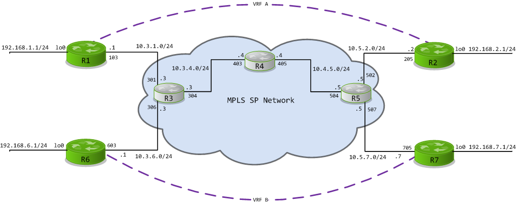
A while back I asked everyone to vote on what topic they wanted to see next, and by no surprise almost every voted for MPLS VRFs. When I started working on this, I decided to take a new approach to these posts, in my previous posts about JunOS Olives I provided ample screen shots and a video demonstrating fully functioning multicast. Today I am going to supply you with a Dynamips configuration file that you can run and follow along as we work within the topology. Here is a link to the file which includes 7 routers and a Frame Relay Switch (for simplicity I connected them all via Frame Relay). Basic MPLS is running over IS-IS on routers 3,4, and 5. All of the interfaces have been configured according to the following diagram. You will need a copy of IOS c3640-jk9o3s-mz.123-14.T7.bin or something for the 3640 that runs MPLS and VRF, check the Cisco Feature Navigator. You will also need to know a little something about Dynamips / Dynagen.
What is a VRF?
One definition describes Virtual Routing and Forwarding (VRF), as a feature that allows you to implement multiple routing tables on the same router. Each VRF is independent and could have the same IP subnets being forwarded to completely different destinations. This is very similar to what were going to be implementing today. VPN Routing and Forwarding, a Layer 3 MPLS VPN technology used to create separate routing tables that we can then forward across the backbone using MultiProtocol BGP (MP-BGP) extensions.
Prep Work
So, I’m going to assume that you’ve at least configured basic frame mode MPLS before. If you haven’t go do it now. Ok, done? It’s dead simple, seriously, all you need to do is setup OSPF or IS-IS on a couple routers, make sure Cisco Express Forwarding (CEF) is turned on ( Router(config)# ip cef ), predefine your MPLS label protocol ( Router(config)#mpls label protocol ldp ), and tell your interfaces you want running mpls, to do so ( Router(config-if)#mpls ip ) … How simple is that??
MPLS Verification
So, we need to verify that the MPLS Label Distribution Protocol (LDP) is doing its job and assigning labels to these routes, right? The following command and output show that our labels are indeed being pushed and popped onto frames.
R3#show mpls forwarding-table
Local  Outgoing    Prefix            Bytes tag  Outgoing   Next Hop
tag    tag or VC   or Tunnel Id      switched   interface
16     Pop tag     10.4.4.4/32       0          Se0/0.304  point2point
17     16          10.5.5.5/32       0          Se0/0.304  point2point
18     Pop tag     10.4.5.0/24       0          Se0/0.304  point2point
19     18          10.5.2.0/24       0          Se0/0.304  point2point
20     19          10.5.7.0/24       0          Se0/0.304  point2point
VRF Configuration
In order to keep things straight in our routing tables, we need to define a few things. First off is the VRF name, this a locally significant label. More important is the Route Distinguisher (RD) value. This is a globaly significant reference to the VRF routing table. In our examples they will be designated as [AS #]:[VPN Instance]. ie 100:1 for VRF_A, and 200:1 for VRF_B. The route-target statements are used for filtering the import and export of VRF routes. Here are the configuration changes needed to setup the VRFs on routers 3 and 5.
!!! R3 !!!
!
ip vrf VPN_A
 rd 100:1
 route-target export 100:1
 route-target import 100:1
!
ip vrf VPN_B
 rd 200:1
 route-target export 200:1
 route-target import 200:1
!
interface Serial0/0.301 point-to-point
 ip vrf forwarding VPN_A
 ip address 10.3.1.3 255.255.255.0
!
interface Serial0/0.306 point-to-point
 ip vrf forwarding VPN_B
 ip address 10.3.6.3 255.255.255.0
!
Notice when you add the interface to a VRF, you need to reconfigure the IP address on it since it was automatically removed by the router. This is done since the route also needs to be moved from the normal routing table into the VRF instance…
!!! R5 !!!
!
ip vrf VPN_A
 rd 100:1
 route-target export 100:1
 route-target import 100:1
!
ip vrf VPN_B
 rd 200:1
 route-target export 200:1
 route-target import 200:1
!
interface Serial0/0.502 point-to-point
 ip vrf forwarding VPN_A
 ip address 10.5.2.5 255.255.255.0
!
interface Serial0/0.507 point-to-point
 ip vrf forwarding VPN_B
 ip address 10.5.7.5 255.255.255.0
!
You will now notice that those interfaces have been removed from the routing table. You can view the view the VRF routing tables via the following commands.
R3#show ip route
Codes: C - connected, S - static, R - RIP, M - mobile, B - BGP
       D - EIGRP, EX - EIGRP external, O - OSPF, IA - OSPF inter area
       N1 - OSPF NSSA external type 1, N2 - OSPF NSSA external type 2
       E1 - OSPF external type 1, E2 - OSPF external type 2
       i - IS-IS, su - IS-IS summary, L1 - IS-IS level-1, L2 - IS-IS level-2
       ia - IS-IS inter area, * - candidate default, U - per-user static route
       o - ODR, P - periodic downloaded static route

Gateway of last resort is not set

     10.0.0.0/8 is variably subnetted, 5 subnets, 2 masks
C       10.3.3.3/32 is directly connected, Loopback0
i L2    10.4.5.0/24 [115/20] via 10.3.4.4, Serial0/0.304
C       10.3.4.0/24 is directly connected, Serial0/0.304
i L2    10.4.4.4/32 [115/20] via 10.3.4.4, Serial0/0.304
i L2    10.5.5.5/32 [115/30] via 10.3.4.4, Serial0/0.304

R3#show ip route vrf VPN_A

Routing Table: VPN_A
Codes: C - connected, S - static, R - RIP, M - mobile, B - BGP
       D - EIGRP, EX - EIGRP external, O - OSPF, IA - OSPF inter area
       N1 - OSPF NSSA external type 1, N2 - OSPF NSSA external type 2
       E1 - OSPF external type 1, E2 - OSPF external type 2
       i - IS-IS, su - IS-IS summary, L1 - IS-IS level-1, L2 - IS-IS level-2
       ia - IS-IS inter area, * - candidate default, U - per-user static route
       o - ODR, P - periodic downloaded static route

Gateway of last resort is not set

     10.0.0.0/24 is subnetted, 1 subnets
C       10.3.1.0 is directly connected, Serial0/0.301

R3#show ip route vrf VPN_B

Routing Table: VPN_B
Codes: C - connected, S - static, R - RIP, M - mobile, B - BGP
       D - EIGRP, EX - EIGRP external, O - OSPF, IA - OSPF inter area
       N1 - OSPF NSSA external type 1, N2 - OSPF NSSA external type 2
       E1 - OSPF external type 1, E2 - OSPF external type 2
       i - IS-IS, su - IS-IS summary, L1 - IS-IS level-1, L2 - IS-IS level-2
       ia - IS-IS inter area, * - candidate default, U - per-user static route
       o - ODR, P - periodic downloaded static route

Gateway of last resort is not set

     10.0.0.0/24 is subnetted, 1 subnets
C       10.3.6.0 is directly connected, Serial0/0.306

R3#
You may also notice that you have apparently lost connectivity to these hosts. That is not exactly the case. The ping command does its normal lookup in the global routing table, in order to find our VRF route we need to specify the soure the ping from the VRF instance.
R3#ping 10.3.1.1

Type escape sequence to abort.
Sending 5, 100-byte ICMP Echos to 10.3.1.1, timeout is 2 seconds:
.....
Success rate is 0 percent (0/5)

R3#ping vrf VPN_A 10.3.1.1

Type escape sequence to abort.
Sending 5, 100-byte ICMP Echos to 10.3.1.1, timeout is 2 seconds:
!!!!!
Success rate is 100 percent (5/5), round-trip min/avg/max = 8/13/20 ms
IGP? Seriously?
So, here is where things get a little funky. We’re going to peer, via our normal IGP with our Service Provider. Yes, you’re going to include your service provider in your IGP. Don’t worry, remember, their interface is in a VRF. Lets get this setup with R1 and R3. I’ll assume you can follow directions and mirror the configuration over to R2 and R5. This is also where things can start getting confusing. You need to keep yoru AS numbers straight, and make sure you’re configuring everything with the right AS at the right time… On VRF_A we’re going to be using EIGRP. Here is the config for R1.
!
router eigrp 100
 network 10.3.1.0 0.0.0.255
 network 192.168.1.0 0.0.0.255
 no auto-summary
!
Looks pretty normal, right? That’s because its exactly the same as if you were just running EIGRP within your own network. However, on the Service Provider side, things are a little more interesting. We start EIGRP with our AS number, but then we activate a new address family for our VRF and configure that as our routing instance. Including something we haven’t seen before, a separate declaration of our Autonomous System number.
router eigrp 65510
 no auto-summary
 !
 address-family ipv4 vrf VPN_A
 network 10.3.1.0 0.0.0.255
 no auto-summary
 autonomous-system 100
 exit-address-family
!
When we take a look at the VRF routing table on R5, we should now see the prefix from R1’s loopback interface.
R3#show ip route vrf VPN_A

Routing Table: VPN_A
Codes: C - connected, S - static, R - RIP, M - mobile, B - BGP
       D - EIGRP, EX - EIGRP external, O - OSPF, IA - OSPF inter area
       N1 - OSPF NSSA external type 1, N2 - OSPF NSSA external type 2
       E1 - OSPF external type 1, E2 - OSPF external type 2
       i - IS-IS, su - IS-IS summary, L1 - IS-IS level-1, L2 - IS-IS level-2
       ia - IS-IS inter area, * - candidate default, U - per-user static route
       o - ODR, P - periodic downloaded static route

Gateway of last resort is not set

     10.0.0.0/24 is subnetted, 1 subnets
C       10.3.1.0 is directly connected, Serial0/0.301
D    192.168.1.0/24 [90/2297856] via 10.3.1.1, 00:03:22, Serial0/0.301
Now, go ahead and configure the same for R2 and R5… Done? Good! Now from Router 5, you should see the loopback interface from R2 in the VRF table.
R5#show ip route vrf VPN_A

Routing Table: VPN_A
Codes: C - connected, S - static, R - RIP, M - mobile, B - BGP
       D - EIGRP, EX - EIGRP external, O - OSPF, IA - OSPF inter area
       N1 - OSPF NSSA external type 1, N2 - OSPF NSSA external type 2
       E1 - OSPF external type 1, E2 - OSPF external type 2
       i - IS-IS, su - IS-IS summary, L1 - IS-IS level-1, L2 - IS-IS level-2
       ia - IS-IS inter area, * - candidate default, U - per-user static route
       o - ODR, P - periodic downloaded static route

Gateway of last resort is not set

     10.0.0.0/24 is subnetted, 1 subnets
C       10.5.2.0 is directly connected, Serial0/0.502
D    192.168.2.0/24 [90/2297856] via 10.5.2.2, 00:01:31, Serial0/0.502
MP-BGP
Now that we have the routing information that we want to exchange on the service provider network, we need to transport. BGP does the heavy lifting here. Multiprotocol-BGP uses BGP communities to send RD and MPLS label encoded messages across the session. The extension that we are using to accomplish this is called VPNv4. Here is the Configuration for R3.
!
router bgp 65510
 neighbor 10.5.5.5 remote-as 65510
 neighbor 10.5.5.5 update-source Loopback0
 !
 address-family vpnv4
 neighbor 10.5.5.5 activate
 neighbor 10.5.5.5 send-community extended
 exit-address-family
 !
Notice that we’re using Router 5’s loopback address as the neighbor address, and setting out own loopback as the update-source. The ‘address-family vpnv4’ command allows us to activate neighbors inside the MP-BGP extension. And the send-community extended command ensures that we’re able to transmit extended BGP communities to our neighbor. Go ahead and mirror this configuration on R5 using 10.3.3.3 as the neighbor address and you should see the BGP session come up.
Redistribution
Since the real meat and potatoes of what we want is the routing information inside of EIGRP, we have to configure some sort of redistribution. Make sure you follow best practices for whatever protocol you’re using.
!!! R3 !!!
router eigrp 65510
 !
 address-family ipv4 vrf VPN_A
 redistribute bgp 65510 metric 100000 100 255 1 1500
 exit-address-family
!
router bgp 65510
 !
 address-family ipv4 vrf VPN_A
 redistribute eigrp 100
 exit-address-family
!
With our setup, you can literally use the same exact redistribution configuration on R5 as you did on R3. And if you did it properly, your routing table should reap the rewards. Full connectivity from R1 <–> R2 !!
R1#show ip route
Codes: C - connected, S - static, R - RIP, M - mobile, B - BGP
       D - EIGRP, EX - EIGRP external, O - OSPF, IA - OSPF inter area
       N1 - OSPF NSSA external type 1, N2 - OSPF NSSA external type 2
       E1 - OSPF external type 1, E2 - OSPF external type 2
       i - IS-IS, su - IS-IS summary, L1 - IS-IS level-1, L2 - IS-IS level-2
       ia - IS-IS inter area, * - candidate default, U - per-user static route
       o - ODR, P - periodic downloaded static route

Gateway of last resort is not set

     10.0.0.0/24 is subnetted, 2 subnets
C       10.3.1.0 is directly connected, Serial0/0.103
D       10.5.2.0 [90/2681856] via 10.3.1.3, 00:19:41, Serial0/0.103
C    192.168.1.0/24 is directly connected, Loopback0
D    192.168.2.0/24 [90/2809856] via 10.3.1.3, 00:19:41, Serial0/0.103
R1#ping 192.168.2.1

Type escape sequence to abort.
Sending 5, 100-byte ICMP Echos to 192.168.2.1, timeout is 2 seconds:
!!!!!
Success rate is 100 percent (5/5), round-trip min/avg/max = 16/28/40 ms
VPN_B
What about VPN_B you ask? Hell, thats for you to figure out. You’ve already got the building blocks there, so go ahead, setup VPN_B using yet another protocol like OSPF or RIP, or I guess you could use EIGRP if you’re scared.. :D
As always if you need any help or have any questions, feel free to leave a comment and I’ll get back to you as soon as I have some time.
The Dynamips topology files for this lab are located here. Please note, I do not provide any copies of Cisco IOS, so please don’t ask.
New posts in your inbox when they publish. No digest, no marketing.