Using OSPF to create unlicensed full duplex connections.
- Tony Mattke
- Routing
- May 9, 2009
- 4 min read
Recently one of my clients asked me to help resolve an issue at an aggregation point on their network. They had several connections that converged onto a single unlicensed link on their network, not only was the link saturated, but it had lots of bi-directional traffic going across it. While I would’ve preferred to move them to a licensed setup, the associated costs were astronomical when compared to implementing a little ospf-fu.
The basic idea here is to create two ospf paths we can use, and on each side ‘de-prefer’ one of them. This allows us to one radio for sending data, and one for receiving data. (although OSPF traffic will still be sent and recieved across either link independently, it should not cause you any issues) This setup creates a simulated full-duplex link. Lets take a look at an example that will for work for Cisco or ImageStream (Quagga) routers…
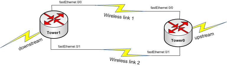
The setup is pretty simple, we’re going to apply a cost of 100 to the interface we wish to not send traffic across. This cost has to be higher than the default cost for whatever interface type you are using. In our example 100 works just fine, its actually a bit of overkill. Lets take a look at the configs on each router.
Tower0:
interface Loopback0
 ip address 1.2.3.4 255.255.255.255
!
interface FastEthernet0/0
 ip address 10.0.100.1 255.255.255.252
!
interface FastEthernet0/1
 ip address 10.0.200.2 255.255.255.252
 ip ospf cost 100
 !
router ospf 1
 router-id 10.0.100.1
 log-adjacency-changes
 redistribute connected subnets
 network 10.0.100.1 0.0.0.0 area 0
 network 10.0.200.2 0.0.0.0 area 0
!
Tower1:
interface Loopback0
 ip address 5.4.3.2 255.255.255.255
!
interface FastEthernet0/0
 ip address 10.0.100.2 255.255.255.252
 ip ospf cost 100
!
interface FastEthernet0/1
 ip address 10.0.200.1 255.255.255.252
!
router ospf 1
 router-id 10.0.200.1
 log-adjacency-changes
 redistribute connected subnets
 network 10.0.100.2 0.0.0.0 area 0
 network 10.0.200.1 0.0.0.0 area 0
!
Now, lets take a look at the routing tables on each.
Tower0:
Tower0#show ip route
Codes: C - connected, S - static, R - RIP, M - mobile, B - BGP
       D - EIGRP, EX - EIGRP external, O - OSPF, IA - OSPF inter area
       N1 - OSPF NSSA external type 1, N2 - OSPF NSSA external type 2
       E1 - OSPF external type 1, E2 - OSPF external type 2
       i - IS-IS, su - IS-IS summary, L1 - IS-IS level-1, L2 - IS-IS level-2
       ia - IS-IS inter area, * - candidate default, U - per-user static route
       o - ODR, P - periodic downloaded static route

Gateway of last resort is not set

     1.0.0.0/32 is subnetted, 1 subnets
C       1.2.3.4 is directly connected, Loopback0
     5.0.0.0/32 is subnetted, 1 subnets
O E2    5.4.3.2 [110/20] via 10.0.100.2, 00:16:59, FastEthernet0/0
     10.0.0.0/30 is subnetted, 2 subnets
C       10.0.100.0 is directly connected, FastEthernet0/0
C       10.0.200.0 is directly connected, FastEthernet0/1
As you can see, on Tower0, we’re using fastEthernet 0/0 to send packets to Tower1, below we should see just the opposite…
Tower1:
Tower1#show ip route
Codes: C - connected, S - static, R - RIP, M - mobile, B - BGP
       D - EIGRP, EX - EIGRP external, O - OSPF, IA - OSPF inter area
       N1 - OSPF NSSA external type 1, N2 - OSPF NSSA external type 2
       E1 - OSPF external type 1, E2 - OSPF external type 2
       i - IS-IS, su - IS-IS summary, L1 - IS-IS level-1, L2 - IS-IS level-2
       ia - IS-IS inter area, * - candidate default, U - per-user static route
       o - ODR, P - periodic downloaded static route

Gateway of last resort is not set

     1.0.0.0/32 is subnetted, 1 subnets
O E2    1.2.3.4 [110/20] via 10.0.200.2, 00:17:45, FastEthernet0/1
     5.0.0.0/32 is subnetted, 1 subnets
C       5.4.3.2 is directly connected, Loopback0
     10.0.0.0/30 is subnetted, 2 subnets
C       10.0.100.0 is directly connected, FastEthernet0/0
C       10.0.200.0 is directly connected, FastEthernet0/1
The routing tables speak for themselves. Obviously I haven’t spoken to the importance of making sure these radios don’t interfere with each other or any other considerations when dealing with the wireless aspect of this configuration as this is a routing tutorial. If you have any questions or if you would like anything explained further, please leave a comment below. Thanks !